SR245 - Computer Interface
SR245
The eight analog I/O channels can be designated through software as all inputs, all outputs, or as a combination of inputs and outputs. All channels have 13 bits of resolution o...
广西科米瑞实验仪器设备有限公司提供 Stanford Research Systems SR245 产品资料、选型咨询、供货报价和售后服务支持,价格面议。
← 返回产品列表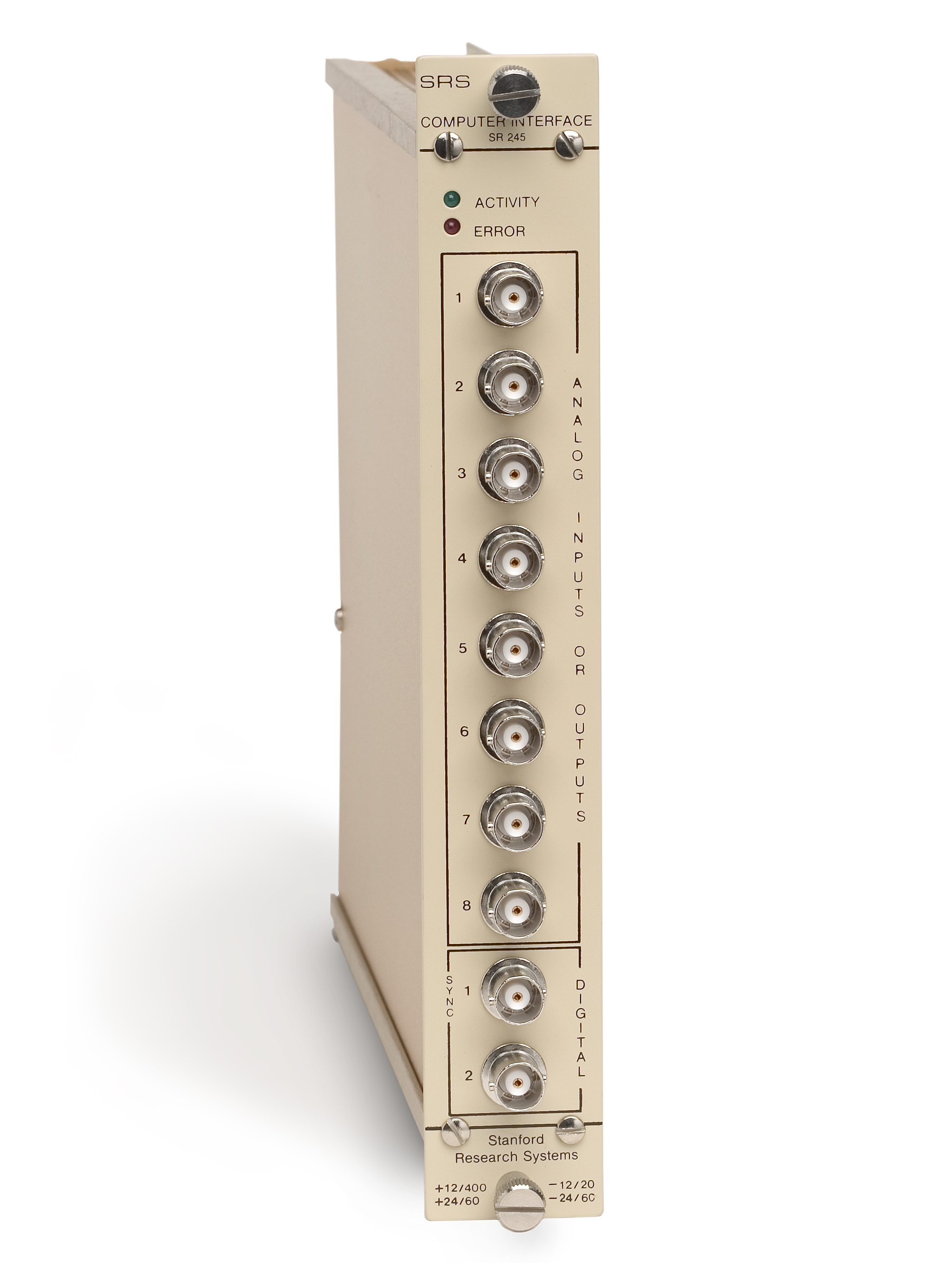
说明
The eight analog I/O channels can be designated through software as all inputs, all outputs, or as a combination of inputs and outputs. All channels have 13 bits of resolution over the ±10.24 VDC full-scale range, with 0.05 % accuracy. Two front-panel digital I/O bits are provided for use as counters or triggers and can be set or read by the computer. Additionally, an 8-bit input and an 8-bit output port are available (on an internal connector) for your own custom digital interfaces. RS-232 and GPIB interfaces Both RS-232 and GPIB interfaces are standard features of the SR245. Simple commands make programming easy from a variety of high level languages—all that's necessary is the ability to send and receive ASCII strings. For example, sending "?5" instructs the module to measure the voltage on the 5 th analog input BNC. Other commands allow you to record in the module's 3500 point buffer memory, ramp an analog output at a specified rate (for gate scanning), or read the contents of a digital counter. SR245 Specifications Any number of the eight ports may be designated under program control as input ports, the rest default to output ports. 1 MΩ impedance, ±10.24 VDC range, protected to 40 VDC. 13-bit resolution (2.5 mV). 0.5 % accuracy. Input offset <2.5 mV. Maximum A/D rate is 2 kHz. <1 Ω impedance. Short circuit current limit is 20 mA. 13-bit resolution (2.5 mV), 0.5 % accuracy. Output offset <2.5 mV Two front-panel I/O TTL bits, one 8-bit digital input port, one 8-bit latched digital output port Input impedances >100 kΩ. Minimum pulse width is 200 ns. Maximum count rate is 4 MHz. Logic one >3 VDC, logic zero <0.7 VDC. Inputs protected to ±10 VDC. Can drive 50 Ω loads to TTL levels IEEE-488 (GPIB) and RS-232 (110 baud to 19.2 kbaud) +24 V/60 mA, 24 V/60 mA, +12 V/20 mA, approx. 8 watts Single-width standard NIM module One year parts and labor on defects in materials and workmanship Input/Output Commands Designates the first n analog ports as inputs, the remainder become outputs. Returns the value of the designated analog port. Returns the value (0 or 1) of the designated digital port. Returns the value of the 8-bit digital input port. Returns the value of the status byte, and clears the status byte. Configures B2 as an input and resets the B2 counter. Returns number of pulses occurring at B2 since the previousC. Sets the analog port n (which must be designated as an output) to the value x (x=-10.237 to +10.237 V) . n=1 to 8 Designates digital bit n as output and sets its value to m (n=1, 2 and m=0, 1) Designates the selected bit as an input (n=1, 2) Sets the 8-bit digital output port to the value n (n=0 to 255) Sets the GPIB SRQ mask to the value (n=0 to 255) Sets the synchronous mode. Responses to commands are returned after next trigger. Sets the asynchronous mode (default). Responses to commands are returned after command is received. Designates every n th pulse at B1 as a trigger (n=1 to 32,767) Masks the trigger input so that no triggers are recognized Unmasks the trigger input Outputs a 10 µs TTL pulse at digital port n (n=1, 2) Outputs a 10 µs TTL pulse at B2 each n th trigger (n=1 to 255)
相关产品
提交需求
请填写必填信息,我们将在工作日尽快回复。