SR250 - Gated Integrator
SR250
Internal rate generator Active baseline subtraction Gate output for precise gate timing Average 1 to 10,000 samples DC to 20 kHz repetition rate
广西科米瑞实验仪器设备有限公司提供 Stanford Research Systems SR250 产品资料、选型咨询、供货报价和售后服务支持,价格面议。
← 返回产品列表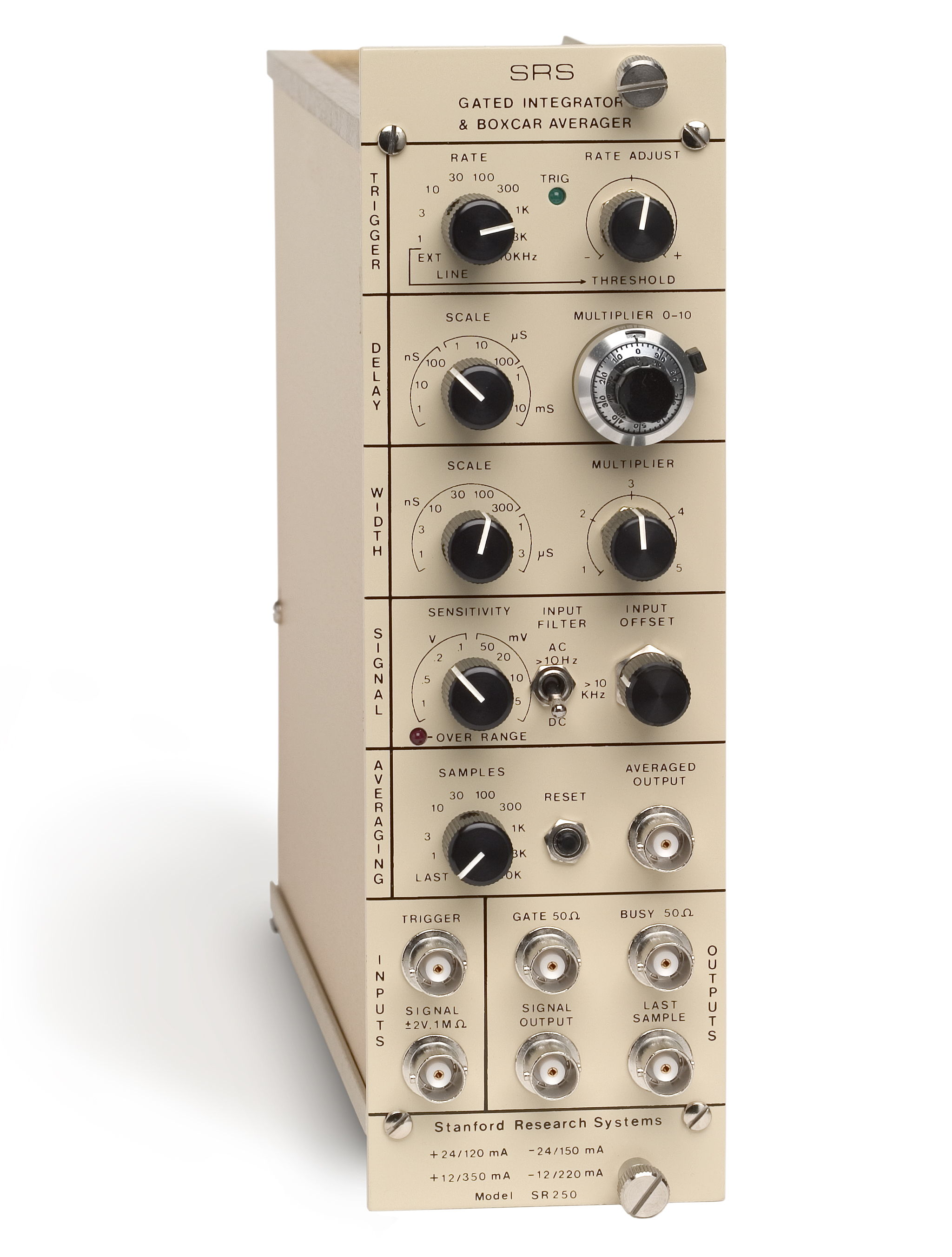
说明
Internal rate generator Active baseline subtraction Gate output for precise gate timing Average 1 to 10,000 samples DC to 20 kHz repetition rate Gate width from 2 ns to 15 µs (expandable to 150 µs) Gate output for precise timing SR250 Gated Integrator The SR250 Gated Integrator is a versatile, high-speed, NIM module designed to recover fast analog signals from noisy backgrounds. The SR250 consists of a gate generator, a fast gated integrator, and exponential averaging circuitry. The gate generator, triggered internally or externally, provides an adjustable delay from a few nanoseconds to 100 ms before it generates a continuously adjustable gate with a width between 2 ns and 15 µs. ... click for SR250 Tech Support Signal Recovery with PMTs Signal Enhancement Boxcar Systems Scientific Instruments DG645 Delay Generator DG535 Delay Generator Signal Recovery — PMTs Signal Enhancement Boxcar Systems Sci. Instruments DG645 Delay Generator DG535 Delay Generator The SR250 Gated Integrator is a versatile, high-speed, NIM module designed to recover fast analog signals from noisy backgrounds. The SR250 consists of a gate generator, a fast gated integrator, and exponential averaging circuitry. The gate generator, triggered internally or externally, provides an adjustable delay from a few nanoseconds to 100 ms before it generates a continuously adjustable gate with a width between 2 ns and 15 µs. The gate delay can be set from the front panel or automatically scanned by applying a rear-panel control voltage. Scanning the gate allows the recovery of entire waveforms. The fast gated integrator integrates the input signal during the gate. The output from the integrator is then normalized by the gate width to provide a voltage proportional to the average of the input signal during the sampling gate. This signal is further amplified and sampled by a low-droop sample-and-hold amplifier, and output via a front-panel BNC connector. The last sample output provides a shot-by-shot analysis of the signal, and makes the instrument a particularly useful component in a computer data acquisition system. The SR250 may be triggered internally or externally. The internal rate generator is continuously variable from 0.5 Hz to 20 kHz in nine ranges. The external trigger pulse may be as short as 5 ns, allowing the unit to be triggered with fast pulses from photodiodes and photomultipliers. Single shot and line triggering can also be selected. The sensitivity of the instrument (volts out / volts in) may be set from 1 V/1 V to 1 V/5 mV. If additional gain is required, the SR250 can be used with the SR240 preamplifier. The input is protected to 100 V and has a 1 MΩ input impedance. An input filter rejects unwanted signals before the input is sampled by the integrator. Unwanted DC input offsets are easily nulled with a 10-turn potentiometer . The delay of the sample gate from the trigger is set by the delay multiplier and scale. The delay scale is multiplied by the setting on the 10-turn multiplier dial, allowing continuously adjustable delays from a few nanoseconds to 100 ms. The delay multiplier may also be changed from the rear-panel control voltage input—a useful feature in applications requiring a scanning gate. Zero to ten volts at this input overrides the front-panel 0 to 10× delay multiplier . Insertion delay from trigger to gate is only 25 ns, and gate-delay jitter is only 20 ps + 0.01 % of the full-scale delay . The width of the sampling gate may be continuously adjusted from 2 ns to 15 µs over eight width ranges. A simple modification of the unit allows gate widths of up to 150 µs. The front-panel gate output provides a representation of the gate that can be overlayed with the signal on an oscilloscope to provide a precise display of the gate timing. A moving exponential average of 1 to 10,000 samples can be selected from the front panel. This traditional averaging technique is useful for pulling small signals from noisy backgrounds. In the case of a random white noise background, the signal-to-noise ratio increases by the square root of the number of samples in the average. This allows a S/N improvement of up to a factor of 100 using this technique alone. If no averaging is desired, or if averaging is to be performed a computer, the last sample output provides a voltage proportional to the average value of the input signal during the last gate period. The reset button sets the average output to zero. The average may also be reset by a rear-panel logic input. The average reset input will accept a TTL signal or a switch closure to ground to reset the moving average output. Polarity Control and Active Baseline Subtraction The polarity of the last sample and averaged outputs is controlled by rear-panel toggle switches. Positive outputs can be selected for negative signals, and vice versa, allowing easy interfacing with unipolar analog-to-digital conversion systems. In addition to the traditional averaging modes, the SR250 possesses a unique Active Baseline Subtraction mode which allows you to actively cancel baseline drift. In the Active Baseline Subtraction mode the SR250 is triggered at twice the source repetition rate. On alternate triggers, when the signal is not present, only the baseline is sampled, and the SR250 inverts the polarity of the last sample output before it is added to the moving average. Thus, any baseline drift not associated with the source will be subtracted out. The signal input is passed on to the signal output by a length of coaxial cable for termination and for gate timing. It is delayed exactly 3.5 ns from the input, and can be terminated to optimize either signal gain or response time. The gate output provides a pulse synchronized with the internal gate signal. The gate output is timed so that it can be overlayed with the signal output for precise adjustment of gate timing. The busy output provides a TTL timing pulse which is high while the unit is integrating, and goes low when the SR250 is ready to accept another trigger. These outputs help simplify experimental setup and troubleshooting. SR250 Specifications The gate generator may be triggered from AC line with adjustable phase. 1 MΩ input impedance. Trigger threshold adjustable from 0.5 to 2 V . Input protected to ±100 VDC. Trigger pulse must be over threshold for >5 ns with a rise time <1 µs. The unit will trigger if trigger threshold is scanned through 0 VDC. LED blinks with each trigger. 0 to 10× using 10-turn dial 2 ns or 5 % of full-scale delay, whichever is larger <20 ps or 0.01 % of full-scale delay, whichever is larger Rear-panel 0 to 10 VDC input overrides front-panel delay multiplier. Input is used by SR200 or SR245 to scan the gate. 1, 3, 10, 30, 100, 300 ns, 1, 3 µs
相关产品
提交需求
请填写必填信息,我们将在工作日尽快回复。