SR255 - Fast Sampler
SR255
Droopless analog output Linear over full range 20 ns insertion delay Trigger rates to 50 kHz 100 ps, 200 ps, 500 ps & 1 ns gates
广西科米瑞实验仪器设备有限公司提供 Stanford Research Systems SR255 产品资料、选型咨询、供货报价和售后服务支持,价格面议。
← 返回产品列表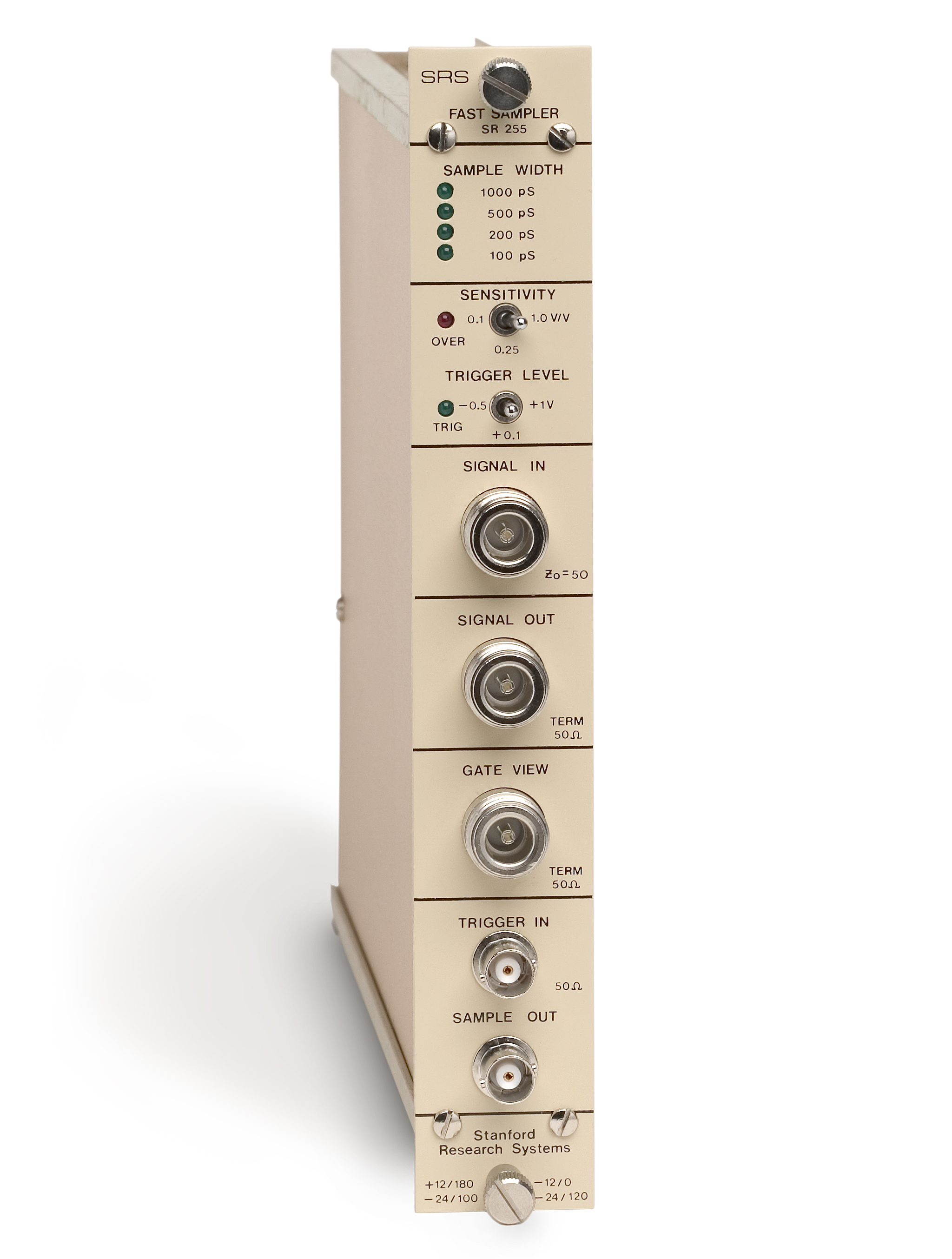
说明
Droopless analog output Linear over full range 20 ns insertion delay Trigger rates to 50 kHz 100 ps, 200 ps, 500 ps & 1 ns gates Jitter less than 2 ps rms SR255 100 ps Gated Integrator The SR255 Fast Sampler module is a gated integrator with four discrete, user-selected gate widths from 100 ps to 1 ns. All of the necessary electronics are built into this high-speed module including an A/D, D/A and a PROM correction circuit to eliminate the inherent non-linearities in the sampling bridge. Signal Recovery with PMTs Boxcar Systems Scientific Instruments DG645 Delay Generator DG535 Delay Generator Signal Recovery — PMTs Boxcar Systems Sci. Instruments DG645 Delay Generator DG535 Delay Generator The SR255 is perfect for fast pulsed experiments where the 2 ns minimum gate width of the SR250 is insufficient. The gate delay is controlled by a rear-panel voltage input which can be supplied by the SR200 Gate Scanner or the SR245 Computer Interface. Convenient gate view and signal outputs allow precise positioning of the gate—particularly important in applications such as time domain reflectometry or shorted-cable baseline subtraction. The SR255 can be used alone, combined with the SR245 Computer Interface module for automated data acquisition, or operated with the SR200 Gate Scanner for scanning gate waveform recovery. The SR255 has a DC coupled trigger input (50 Ω) that supports trigger rates up to 50 kHz. The trigger threshold can be set to -0.5 V, +0.1 V or +1 V on the front panel. For reliable triggering, the trigger must remain over threshold for at least 5 ns and not exceed 5 V. The delay from trigger to sample is controlled by an analog voltage applied at the rear of the unit. You can select delay ranges of 1, 10, 100 or 1000 ns/V with four switches accessed through the instrument's side panel. In addition to the adjustable delay, there is a fixed insertion delay of about 20 ns. With only 2 ps rms gate jitter, the SR255 makes it easy to set up and maintain precise gate timing. Four fixed gate widths of 100 ps, 200 ps, 500 ps and 1000 ps can be selected. A front-panel LED indicates which gate width is being used. The SR255 is designed to be used with RG58A cable. To achieve an optimally flat response, two meters of RG58A cable should be used with a BNC to N-Type converter (provided with each SR255). The frequency response of the SR255's front end has been peaked above 2 GHz to compensate for the losses in 2 meters of cable, and so this length of cable is recommended for the signal input line. The signal input is passed to the signal out BNC via an internal 300 ps delay line. The signal output should be terminated in 50 Ω with a high quality terminator to minimize reflections and pulse distortion. The signal output aids in synchronizing the sample with the gate. The input signal should not exceed the sensitivity selection on the front panel, as the input is only protected to +5 VDC. Gate View and Fast Timing You can use the gate view output to time the sample gate with respect to the signal. The leading edge of the gate view output (50 ps rise time) indicates when the sample gate is being opened. The output is a pulse of approximately 3 V with an exponential decay of about 4 ns. The sensitivity of the module (Vin/Vout) can be set to 1 V/V, 0.25 V/V or 0.1 V/V. For example, when 0.1 V/V sensitivity is selected, a 100 mV input will produce a 1 V output. The red overload LED will come on when the output exceeds 1 V. Analog and Digital Outputs The SR255 has both analog and digital outputs making it easy to interface in a wide range of experiments. The sample output provides a ±1 VDC full-scale analog voltage proportional to the value of the signal during the gate interval. Resolution is 0.5 % of full scale, and the output can drive up to 10 mA. This output is available 20 µs after the signal is sampled. Each unit is custom linearized with a PROM to ensure excellent linearity and full dynamic range. The Fast Sampler also provides a digital interface through a 15-pin connector on the rear panel of the module. This interface is a parallel, binary interface which may be connected to either the 20-pin connector on the circuit board of the SR245 Computer Interface module or to any 8-bit digital I/O port. SR255 Specifications -0.5, +0.1 or +1 VDC 20 ns + (delay range) × (control voltage). Control voltage input is on the rear. 1, 10, 100 or 1000 ns/V 100, 200, 500, 1000 ps N-type connector. Leading edge indicates when gate opens. ±50 ps with respect to signal out N-Type connector. Characteristic impedance is 50 Ω. Protected to 5 VDC. The full-scale input level equals the sensitivity setting. 200 µV rms (1000 ps gate) 350 µV rms (500 ps gate) 600 µV rms (200 ps gate) 800 µV rms (100 ps gate) 0.1, 0.25, or 1.0 V full scale. Over range LED indicates signal greater than full scale. The SIGNAL IN is passed to the SIGNAL OUT for termination, gate timing and special applications such as time domain reflectometry. There is a 300 ps delay between signal in and signal out.
相关产品
提交需求
请填写必填信息,我们将在工作日尽快回复。